
The tank scans for targets via the self-made infra red scanner, aims in yaw axis by rotating the complete chassis and attacks the target with a airsoft gun.
The scanner detects white targets reflecting more infra red light than the background. Therefore the light of a modified IR-LED is focused by a lens to a light beam. A standard television IR-receiver detects if the beam gets reflected by a white target. The sensor head is turned by a step motor and scans the surrounding area, similar to a radar antenna.
The following video shows the tank in action aiming at the white bucket at a range of about three to five meters. (For more videos see my YouTube channel)
I developed this tank for a school project in 2008. The project consists of the tank’s hardware (e.g. chassis made of LEGO, microcontrollers, motor drivers) and the software written in Assembler. Full Documentation of the infrared tank project (in German) can be downloaded as PDF.
Technical Details
In the following some technical details of the tank’s construction and implementation are discussed.
Overview and Components
The following figure shows the tank’s main components:
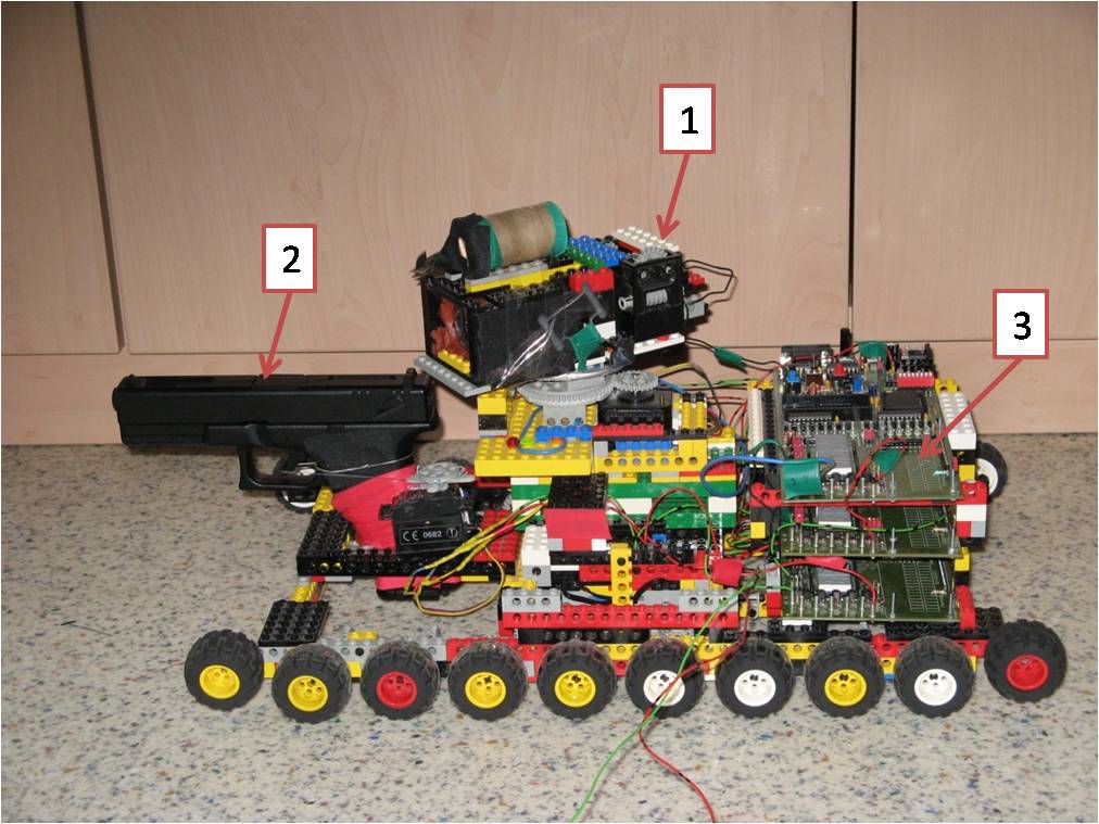
- Self-made infrared scanner for target detection
- Airsoft gun used as canon to attack targets and
- Three microcontroller boards controlling the tank
The topmost controller board generates the infrared signal following the RC5 protocol (read more on this in the scanner section). The board in the middle controls the scanner head, detects targets by evaluating the signal of the receiver and triggers the attack. Below that board is the microcontroller controlling the chassis. Whenever the controller in the middle detects a target, it sends the chassis controller a turn angle to navigate to via serial interface.
Chassis and superstructure
Chassis and superstructure of the tank as well as the infrared secanner are build of LEGO Technic. LEGO makes it possible to easily construct and modify mechanical system without the need for tools. The following figure shows the chassis.
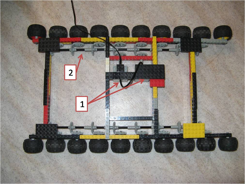
- Two electric motors for each side. A single motor doesn’t have enough power.
- Common shaft for one side connectiong eight of the ten wheels.
As already mentioned in the overview, the chassis and therefore the driving is controlled by a dedicated microcontoller. In the following this one is called Drive-MC.
In order to control the electric motors, a motor driver is needed. This is due to the fact, that the microcontroller can’t supply enough current and needs to be protected from induction voltage peeks. The tank uses a standard L298 motor driver to achieve this (datasheet).
Infrared scanner and targeting system
The tank’s scanner head uses infrared light to detect white targets reflecting more infrared light than their surroundings. The basic mechanism of the scanner can be compared to the one of a radar antenna. A radar antenna emits radar waves in a direction and evaluates the reflected signal. If there’s a reflection at a certain angle it means there is an object in this direction.
The scanner of the tank applies the same principle, but uses infrared light instead of radar waves. Like a radar antenna, the scanner’s direction is continuosly changed to scan a wide one-dimensional area.
The figure below shows the scanner head with it’s components.
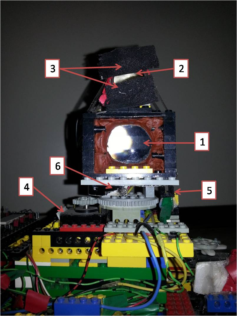
- Lens to focus infra red beam of modified IR LED
- Sensor lens to focus infra red light reflected by target
- Aperture for sensor (realized via black tape)
- Step motor to rotate the scanner head
- Photoelectric barrier to detect 0° position (line of fire)
- Shutter for photoelectric barrier to detect 0° position
Draft of the infrared targeting system
The following draft explains the principles of the infrared targeting system.

- Modified infrared LED LD274 (The tip of the LED is planed to get rid of the lens effect)
- Lens to focus infrared light of IR LED to increase range and improve accuracy
- Focused infrared beam
- White target reflecting the infrared light
- Reflected infrared light
- Lens to focus the reflected infrared light reflected from the target onto the sensor
- Infrared sensor TSOP1733
In (1) the modified LED is used to emit the infrared light needed to detect targets. The lens in (2) focuses the emited infrared light to a beam. This has two advantages. A beam does not loose its intensity over distance. This extends the detection range. The second advantage is that the beam lights only a small area in the recent scan direction. As usual LEDs also have a lense effect, the tip of the LED has been flattened to get rid of this effect. Otherwise this would influence the light cone and make it harder to find the focal point.
Whenever the focused light beam (3) hits a surface (4) two cases may occur:
- The surface reflects only little infrared light (for example a black wall) or the surface is far away and therefore only a little amount of the reflected light returns to the sensor (7). In this case, the sensor doesn’t recognize the signal and no target is detected.
- The surface reflects enough infrared light and is not to far away. In this case some of the reflected light (5) reaches the lens of the sensor system (6). Again this lense is used to focus the light and therefore to increase the detectability radius. The infrared sensor (7) is then able to detect the signal and thus the tank detects a target at the current turn angle of the sensor head.
Protection against false-positive detections
Since the infrared targeting system uses infrared light, a number of erroneous detections might occur. These could be caused by other sources of infrared light like the sun or hot objects (e.g light bulbs).
In order to keep the the implementation simple but also achieve a good false-positive protection, a standard IR-sensor is used. The TSOP1733 is a standard sensor used for data transmissions via infrared light. Thus it is insensitive to most sources of error. The usage of the RC5 protocol increases the protection even more.
However the drawback of using the TSOP1733 sensor is that the singal must follow a standard protocoll (the tank uses RC5) and have a frequency of 33 kHz. As the used microcontrollers can only execute one million operations a second, there weren’t much commands left to generate the signal. This is why the topmost controller is solely used to generate the IR-signal. There is simply no calculation power left.
Airsoft gun used as the tank’s canon
As the tank is able to detect target’s it also needs a canon to attack them. For this task a JLS 2011B AEG airsoft gun is used. This gun can be used in automatic and semi-automatic mode, whereas the latter one is used by the tank. In order to fire the gun without the need to deconstruct it, a model servo motor pulls the trigger. To connect the servo and the trigger, dental floss is used, as it doesn’t elongate over time.
The following figure shows the airsoft gun glued to some LEGO parts to be able to mount it on the tank. This also allows an easy dismounting to refill the gun’s ammo.
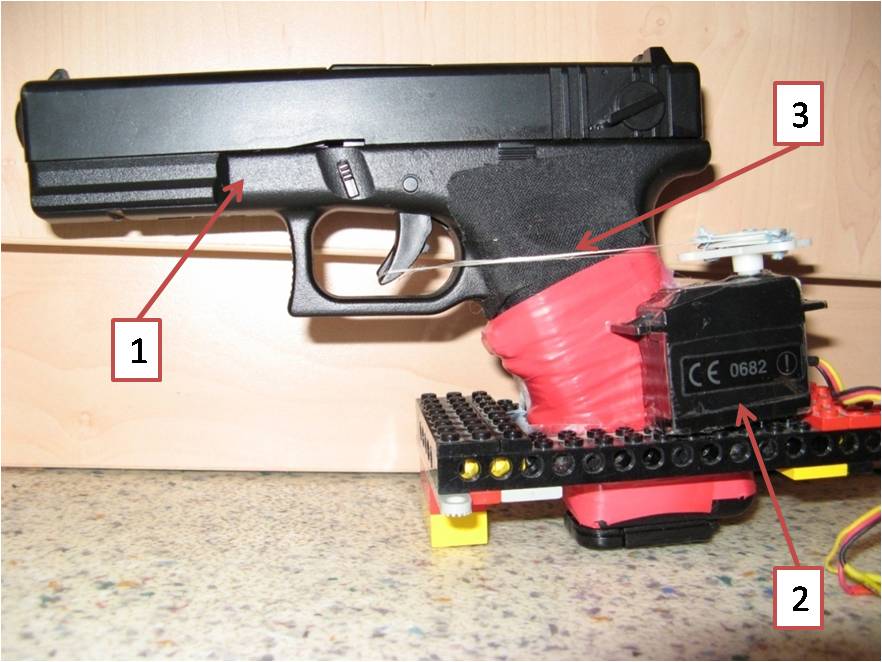
- Airsoft gun JLS 2011B
- Model servo motor to pull the trigger
- Dental floss to connect the servo motor with the trigger
 Project Kammerjäger (PSE)